Connect to the Dev Board I/O pins
The Dev Board provides access to several peripheral interfaces through the 40-pin expansion header, including GPIO, I2C, UART, and SPI. This page describes how you can interact with devices connected to these pins.
Because the Dev Board runs Mendel
Linux, you can interact with the
pins from user space using Linux interfaces such as device files (/dev) and sysfs files
(/sys). There are also several API libraries you can use to program the peripherals connected to
these pins. This page describes a few API options, including python-periphery, Adafruit Blinka, and
libgpiod.
All I/O pins on the 40-pin header are powered by the 3.3 V power rail, with a programmable impedance of 40-255 ohms, and a max current of ~82 mA.
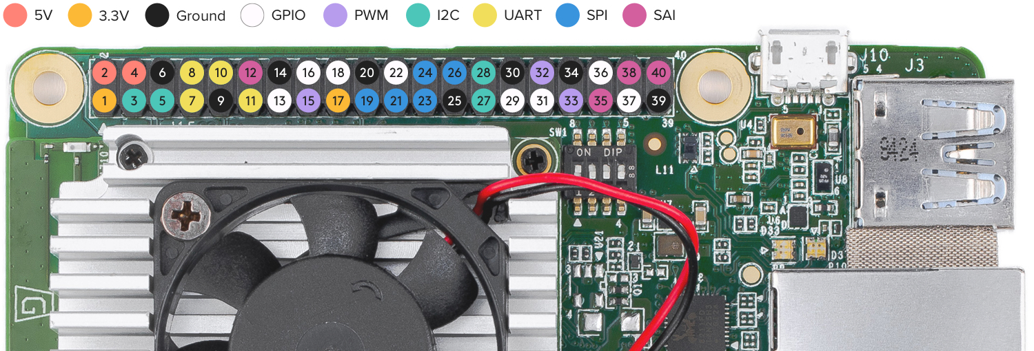
Header pinout
Table 1 shows the header pinout, including the device or sysfs file for each pin, plus the character
device numbers. For a pinout that includes the SoC pin names see the Dev Board
datasheet instead.
You can also see the header pinout from the command line by typing pinout on the Dev Board.
| Chip, line | Device path | Pin function | Pin | Pin function | Device path | Chip, line | |
|---|---|---|---|---|---|---|---|
| +3.3 V | 1 | 2 | +5 V | ||||
| /dev/i2c-1 | I2C2_SDA | 3 | 4 | +5 V | |||
| /dev/i2c-1 | I2C2_SCL | 5 | 6 | Ground | |||
| /dev/ttymxc2 | UART3_TXD | 7 | 8 | UART1_TXD | /dev/ttymxc0 | ||
| Ground | 9 | 10 | UART1_RXD | /dev/ttymxc0 | |||
| /dev/ttymxc2 | UART3_RXD | 11 | 12 | SAI1_TXC | |||
| 0, 6 | /sys/class/gpio/gpio6 | GPIO_P13 | 13 | 14 | Ground | ||
| 2, 0 | /sys/class/pwm/pwmchip2/pwm0 | PWM3 | 15 | 16 | GPIO_P16 | /sys/class/gpio/gpio73 | 2, 9 |
| +3.3 V | 17 | 18 | GPIO_P18 | /sys/class/gpio/gpio138 | 4, 10 | ||
| /dev/spidev0 | ECSPI1_MOSI | 19 | 20 | Ground | |||
| /dev/spidev0 | ECSPI1_MISO | 21 | 22 | GPIO_P22 | /sys/class/gpio/gpio140 | 4, 12 | |
| /dev/spidev0 | ECSPI1_SCLK | 23 | 24 | ECSPI1_SS0 | /dev/spidev0.0 | ||
| Ground | 25 | 26 | ECSPI1_SS1 | /dev/spidev0.1 | |||
| /dev/i2c-2 | I2C3_SDA | 27 | 28 | I2C3_SCL | /dev/i2c-2 | ||
| 0, 7 | /sys/class/gpio/gpio7 | GPIO_P29 | 29 | 30 | Ground | ||
| 0, 8 | /sys/class/gpio/gpio8 | GPIO_P31 | 31 | 32 | PWM1 | /sys/class/pwm/pwmchip0/pwm0 | 0, 0 |
| 1, 0 | /sys/class/pwm/pwmchip1/pwm0 | PWM2 | 33 | 34 | Ground | ||
| SSAI1_TXFS | 35 | 36 | GPIO_P36 | /sys/class/gpio/gpio141 | 4, 13 | ||
| 2, 13 | /sys/class/gpio/gpio77 | GPIO_P37 | 37 | 38 | SAI1_RXD0 | ||
| Ground | 39 | 40 | SAI1_TXD0 | ||||
For further information on the various interfaces, see the i.MX 8M Dual/8M QuadLite/8M Quad Applications Processors Reference Manual.
Program with python-periphery
The python-periphery library provides a generic Linux interface that's built atop the sysfs and character device interface, providing APIs to control GPIO, PWM, I2C, SPI, and UART pins.
You can install the library on your Dev Board as follows:
python3 -m pip install python-peripheryThe Periphery library allows you to select a GPIO or PWM pin with a pin number. Other interfaces, such as I2C and UART pins must be specified using the pin's device path. See the following examples.
GPIO
You can instantiate a GPIO object using either the sysfs path (deprecated) or the character device numbers.
The following code instantiates each GPIO pin as input using the character devices:
gpio_p13 = GPIO("/dev/gpiochip0", 6, "in")
gpio_p18 = GPIO("/dev/gpiochip4", 10, "in")
gpio_p22 = GPIO("/dev/gpiochip4", 12, "in")
gpio_p29 = GPIO("/dev/gpiochip0", 7, "in")
gpio_p31 = GPIO("/dev/gpiochip0", 8, "in")
gpio_p36 = GPIO("/dev/gpiochip4", 13, "in")

gpio_p16 = GPIO("/dev/gpiochip2", 9, "out")
gpio_p37 = GPIO("/dev/gpiochip2", 13, "out")For example, here's how to turn on an LED when you push a button:
from periphery import GPIO

led = GPIO("/dev/gpiochip2", 13, "out")  # pin 37
button = GPIO("/dev/gpiochip4", 13, "in")  # pin 36

try:
  while True:
    led.write(button.read())
finally:
  led.write(False)
  led.close()
  button.close()
For more examples, see the periphery GPIO documentation.
PWM
The following code shows how to instantiate each of the PWM pins with Periphery:
pwm1 = PWM(0, 0)
pwm2 = PWM(1, 0)
pwm3 = PWM(2, 0)
For usage examples, see the periphery PWM documentation.
I2C
The following code shows how to instantiate each of the I2C ports with Periphery:
i2c2 = I2C("/dev/i2c-1")
i2c3 = I2C("/dev/i2c-2")
For usage examples, see the periphery I2C documentation.
SPI
The following code shows how to instantiate each of the SPI ports with Periphery:
# SPI1, SS0, Mode 0, 10MHz
spi1_0 = SPI("/dev/spidev0.0", 0, 10000000)
# SPI1, SS1, Mode 0, 10MHz
spi1_1 = SPI("/dev/spidev0.1", 0, 10000000)
For usage examples, see the periphery SPI documentation.
Permission denied error when trying
to access the SPI device, it should be fixed if you run the following:
sudo apt-get update && sudo apt-get dist-upgrade

sudo reboot now
UART
The following code shows how to instantiate each of the UART ports with Periphery:
# UART1, 115200 baud
uart1 = Serial("/dev/ttymxc0", 115200)
# UART3, 9600 baud
uart3 = Serial("/dev/ttymxc2", 9600)systemctl stop serial-getty@ttymxc0.service
For usage examples, see the periphery Serial documentation.
Program with Adafruit Blinka
The Blinka library not only offers a simple API for GPIO, PWM, I2C, and SPI, but also provides compatibility with a long list of sensor libraries built for CircuitPython. That means you can reuse CircuitPython code for peripherals that was originally used on microcontrollers or other boards such as Raspberry Pi.
To get started, install Blinka and libgpiod on your Dev Board Mini as follows:
sudo apt-get install python3-libgpiod

python3 -m pip install adafruit-blinka
Then you can turn on an LED when you push a button as follows (notice this uses pin names from the pinout above):
import board
import digitalio

led = digitalio.DigitalInOut(board.GPIO_P37)  # pin 37
led.direction = digitalio.Direction.OUTPUT

button = digitalio.DigitalInOut(board.GPIO_P36)  # pin 36
button.direction = digitalio.Direction.INPUT

try:
  while True:
    led.value = button.value
finally:
  led.value = False
  led.deinit()
  button.deinit()
For more information, including example code using I2C and SPI, see the Adafruit guide for CircuitPython libraries on Coral. But we suggest you skip their setup guide and install Blinka as shown above. Also check out the Blinka API reference.
Program GPIOs with libgpiod
You can also interact with the GPIO pins using the libgpiod library, which provides both C++ and Python API bindings. But libgpiod is for GPIOs only, not any digital protocols. (The Blinka library uses libgpiod as its implementation for GPIOs.)
There's currently no online API docs for libgpiod, but the source code is fully documented. If you clone the repo, you can build C++ docs with Doxygen. For Python, you can install the libgpiod package and print the API docs as follows:
sudo apt-get install python3-libgpiod

python3 -c 'import gpiod; help(gpiod)'
Then you can turn on an LED when you push a button as follows:
import gpiod

CONSUMER = "led-demo"
chip2 = gpiod.Chip("2", gpiod.Chip.OPEN_BY_NUMBER)
chip4 = gpiod.Chip("4", gpiod.Chip.OPEN_BY_NUMBER)

led = chip2.get_line(13)  # pin 37
led.request(consumer=CONSUMER, type=gpiod.LINE_REQ_DIR_OUT, default_vals=[0])
button = chip4.get_line(13)  # pin 36
button.request(consumer=CONSUMER, type=gpiod.LINE_REQ_DIR_IN)

try:
  while True:
    led.set_value(button.get_value())
finally:
  led.set_value(0)
  led.release()
  button.release()
Is this content helpful?