Set up the Wireless Add-on board
The Coral Wireless Add-on board provides Wi-Fi and Bluetooth functionality for the Coral Dev Board Micro. This page shows how to connect the boards and start developing with Wi-Fi and Bluetooth. Additionally, the Wireless Add-on exposes JTAG pins for debugging.
For technical details, see the Coral Wireless Add-on datasheet.
Connect the boards together
Carefully press the boards together as follows:
-
Orient the boards to align the board-to-board connectors and mounting holes.
Caution: Do not to press on the camera lens or you might damage the sensor. -
Pinch the boards together using a flat part of the board near the connectors (it's okay to press on the mounted chips).
You should hear a firm click.
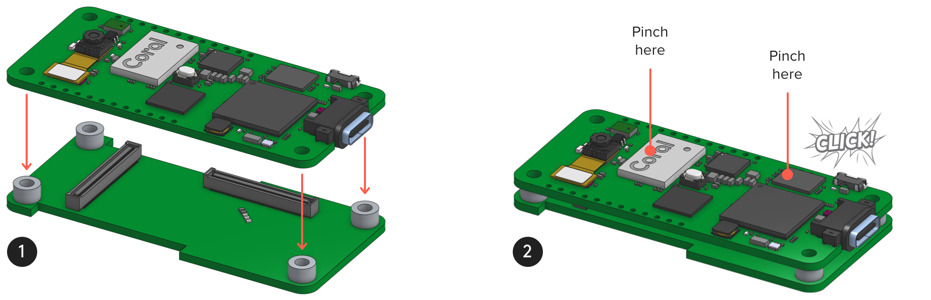
When viewed from the side, the boards should be perfectly aligned and the four standoffs should be touching the main board.
Connect to Wi-Fi
To get online with FreeRTOS, include coralmicro/libs/base/wifi.h and then
call coralmicro::WiFiTurnOn()
and coralmicro::WiFiConnect().
You can specify your network details with coralmicro::WiFiConnect() or set
default network details when you flash the board using the --wifi_ssid and
--wifi_psk arguments.
For example, try the curl example with your own network name and password
(run this from the coralmicro repo root):
bash build.sh

python3 scripts/flashtool.py -e curl --subapp curl_wifi \
        --wifi_ssid NETWORK_NAME --wifi_psk NETWORK_PASSWORD
You should see output in the serial console like this:
Attempting to use Wi-Fi...
failed to read back country, returning WW
WLAN MAC Address : E8:4F:25:5C:27:57
WLAN Firmware    : wl0: May  2 2019 02:46:20 version 7.45.189 (r714228 CY) FWID 01-105ab14e
WLAN CLM         : API: 12.2 Data: 9.10.136 Compiler: 1.29.4 ClmImport: 1.36.3 Creation: 2019-05-02 02:31:24
Wi-Fi connected
DHCP succeeded, our IP is 192.168.86.54.
www.example.com -> 93.184.216.34
Curling http://www.example.com:80/
Curling of http://www.example.com:80/ successful! (1256 bytes curled)
Done.
Connect with Bluetooth devices
The Wireless Add-on provides support for both classic Bluetooth and Bluetooth low-energy.
To make the board discoverable or find and connect to other Bluetooth devices,
you just need to include
coralmicro/libs/nxp/rt1176-sdk/edgefast_bluetooth/edgefast_bluetooth.h.
For any Bluetooth task, you must first call InitEdgefastBluetooth() to
initialize the Bluetooth stack and configure board-specific settings.
Then you can use the Bluetooth APIs to
advertise the board and discover other devices with Bluetooth.
For example, try the following example to scan for local devices:
bash build.sh

python3 scripts/flashtool.py -e ble_beacon_scan
To see the discovered devices, you need to connect to the serial console.
Debug with GDB
The Wireless Add-on board exposes JTAG pins that allow you to debug your apps with GDB. (Or you can expose the JTAG pins with your own add-on board—see section 5.14 in the Dev Board Micro datasheet.)
Requirements
- Any JTAG tool that supports the MIMXRT1176CVM8A should work. However, we've tested only the JLink Base with a Linux host.
- A 2x5 header soldered onto the JTAG pads (J4) on the Wireless Add-on (or on a custom add-on board with the JTAG pins exposed).
Set up the software
Get set up for JTAG debugging as follows:
-
Install JLink. Take note of the JLink installation path if you're not on Linux and it's something other than
/opt/SEGGER/JLink. -
Open
coralmicro/third_party/modified/nxp/rt1176-sdk/pin_mux.cand comment-out the following lines to change the muxing for pins shared with SPI:// Comment-out these lines to enable JTAG IOMUXC_SetPinMux(IOMUXC_GPIO_LPSR_10_GPIO_MUX6_IO10, 0U); IOMUXC_SetPinMux(IOMUXC_GPIO_LPSR_11_GPIO_MUX6_IO11, 0U); IOMUXC_SetPinMux(IOMUXC_GPIO_LPSR_12_GPIO_MUX6_IO12, 0U);Notice: These pins are also routed to the right-side header pins (J10 pins 6, 7, and 8), so those header pins will be inaccessible after this change. -
Open
coralmicro/third_party/modified/FreeRTOS/FreeRTOSConfig.hand comment-out the following line to disable CPU sleep:
#define configUSE_TICKLESS_IDLE 2-
Rebuild the repo (run this from the
coralmicroroot):bash build.sh
Flash for debugging
To flash your app with the debugging symbols intact and start the GDB server,
just add the --debug flag. However, the --debug flag flashes your app to
RAM instead of to flash memory (the board must remain running in order for the
debugger to connect). Thus, if your app includes data that must be loaded to
the flash filesystem (such as a .tflite file), then you need to first flash
the app normally to put the data on the flash memory. Then you can you start
the debugger. For example:
# First flash all app data to the flash memory:
python3 scripts/flashtool.py -e detect_faces

# Then flash for debugging:
python3 scripts/flashtool.py -e detect_faces --debug/opt/SEGGER/JLink (the Linux default), so if JLink
is somehwere else on your system, you must specify the location with the
--jlink_path argument.
When debug mode is done flashing, it runs your app under GDB and flashtool starts the GDB server in your current terminal.
To stop execution and interact with the debugger, press CTRL + C.
To revise the GDB commands that run our app, open scripts/flashtool.py and
edit the StateStartGdb function.
Is this content helpful?