Dev Board datasheet
Features
- Edge TPU System-on-Module (SoM)
- NXP i.MX 8M SoC (Quad-core Arm Cortex-A53, plus Cortex-M4F)
- Google Edge TPU ML accelerator coprocessor
- Cryptographic coprocessor
- Wi-Fi 2x2 MIMO (802.11b/g/n/ac 2.4/5 GHz)
- Bluetooth 4.2
- 8 or 16 GB eMMC
- 1 or 4 GB LPDDR4
- USB connections
- USB Type-C power port (5 V DC)
- USB 3.0 Type-C OTG port
- USB 3.0 Type-A host port
- USB 2.0 Micro-B serial console port
- Audio connections
- 3.5 mm audio jack (CTIA compliant)
- Digital PDM microphone (x2)
- 2.54 mm 4-pin terminal for stereo speakers
- Video connections
- HDMI 2.0a (full size)
- 39-pin FFC connector for MIPI DSI display (4-lane)
- 24-pin FFC connector for MIPI CSI-2 camera (4-lane)
- MicroSD card slot
- Gigabit Ethernet port
- 40-pin GPIO expansion header
- Supports Mendel Linux (derivative of Debian)
Overview
The Coral Dev Board is a single-board computer that's ideal when you need to perform fast machine learning (ML) inferencing in a small form factor. You can use the Dev Board to prototype your embedded system and then scale to production using the on-board Coral System-on-Module (SoM) combined with your custom PCB hardware.
The SoM provides a fully-integrated system, including NXP's iMX 8M system-on-chip (SoC), eMMC memory, LPDDR4 RAM, Wi-Fi, and Bluetooth, but its unique power comes from Google's Edge TPU coprocessor. The Edge TPU is a small ASIC designed by Google that provides high performance ML inferencing with a low power cost. For example, it can execute state-of-the-art mobile vision models such as MobileNet v2 at almost 400 FPS, in a power efficient manner.
The baseboard provides all the peripheral connections you need to prototype a project, including USB 2.0/3.0 ports, DSI display interface, CSI-2 camera interface, Ethernet port, speaker terminals, and a 40-pin I/O header.
Key benefits of the Dev Board:
- High-speed and low-power ML inferencing (4 TOPS @ 2 W)
- A complete Linux system (running Mendel, a Debian derivative)
- Prototyping and evaluation board for the small Coral SoM (40 x 48 mm)
Ordering information
| Part number | Description |
|---|---|
| G950-01455-01 G950-03970-01 G950-04742-01 |
Coral Dev Board with 1 GB RAM and 8 GB eMMC (part number varies by region) |
| G950-06210-01 | Coral Dev Board with 4 GB RAM and 16 GB eMMC |
Table of contents
System components
| Feature | Details |
|---|---|
| Main system-on-chip (i.MX8M) | |
| Arm Cortex-A53 MPCore platform |
Quad symmetric Cortex-A53 processors:
Support of 64-bit Armv8-A architecture:
|
| Arm Cortex-M4 core platform |
|
| Graphic Processing Unit (GPU) |
|
| Video Processing Unit (VPU) |
|
| I/O connectivity |
Note: The list above is the number of signals available to the baseboard (after considering SoC signals used by the SoM). |
| On-chip memory |
|
| External memory |
|
| Display | HDMI Display Interface:
MIPI-DSI Display Interface:
|
| Audio |
|
| Camera |
|
| Security |
|
| ML accelerator | |
| Edge TPU coprocessor |
|
| Memory and storage | |
| Random access memory (SDRAM) |
|
| Flash memory (eMMC) |
|
| Expandable flash (MicroSD) |
|
| Network & wireless | |
| Ethernet |
|
| Wi-Fi |
Murata LBEE5U91CQ module:
|
| Bluetooth |
Murata LBEE5U91CQ module:
|
| Security | |
| Cryptographic coprocessor |
Microchip ATECC608A cryptographic coprocessor:
|
| Baseboard | |
| Connectors |
|
Block diagrams
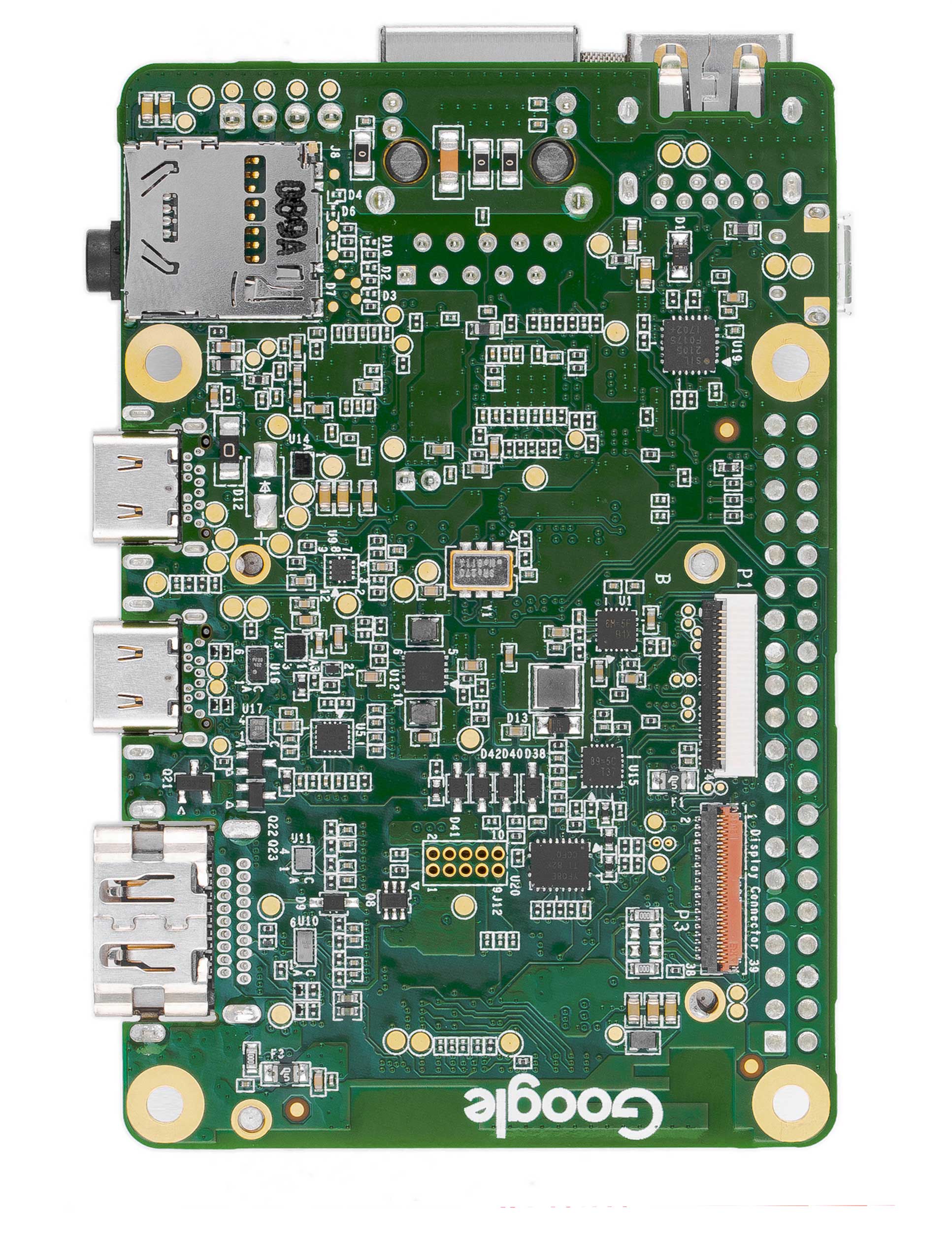
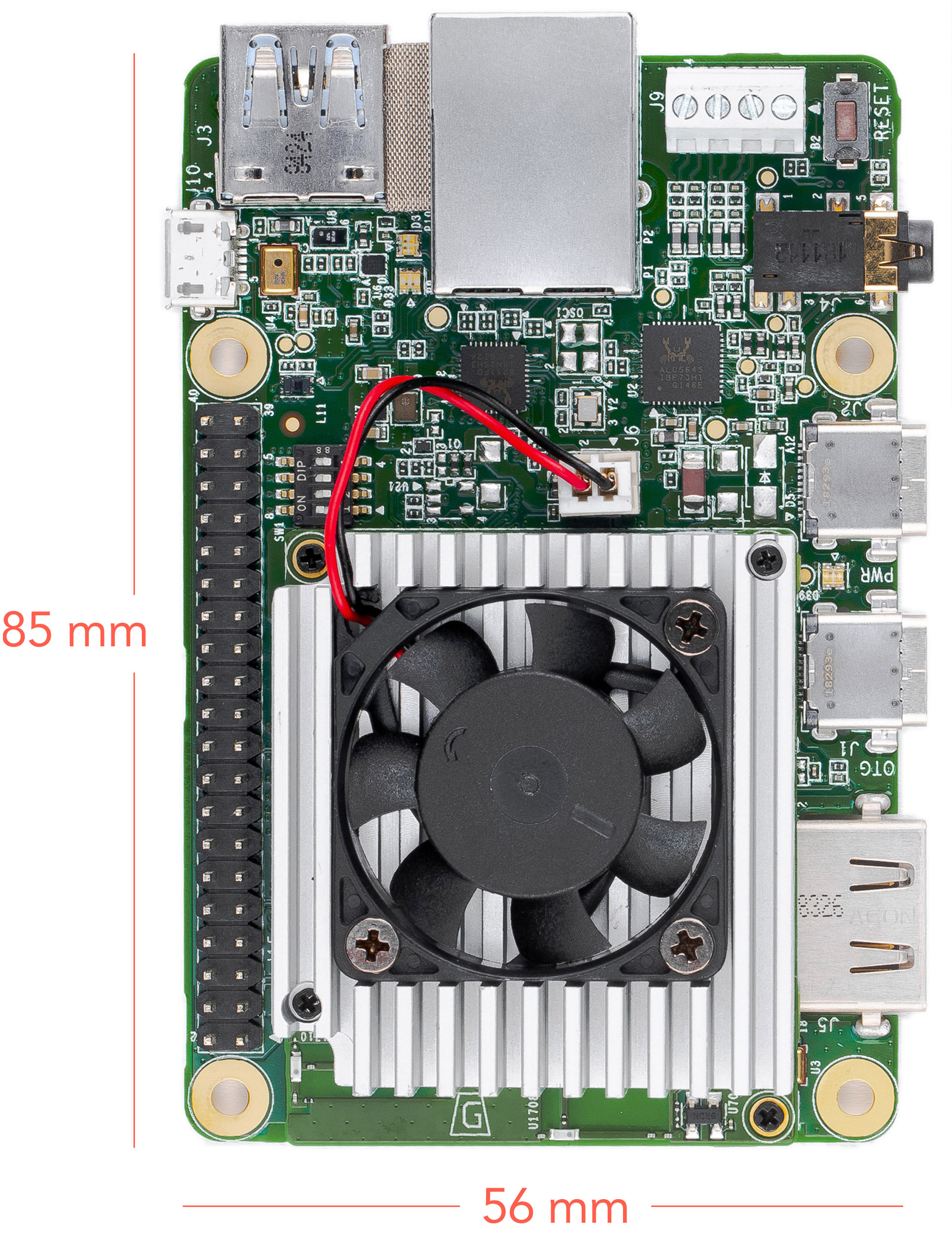
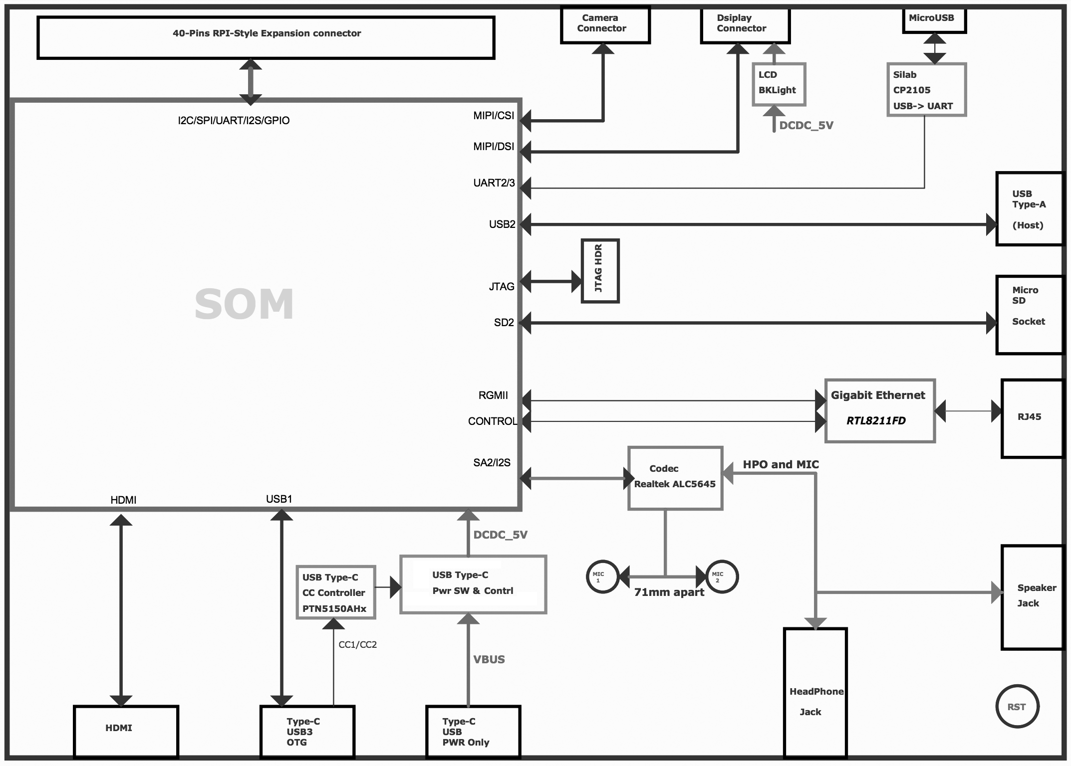
Figures 1 and 2 illustrate the core components on the baseboard and SoM.
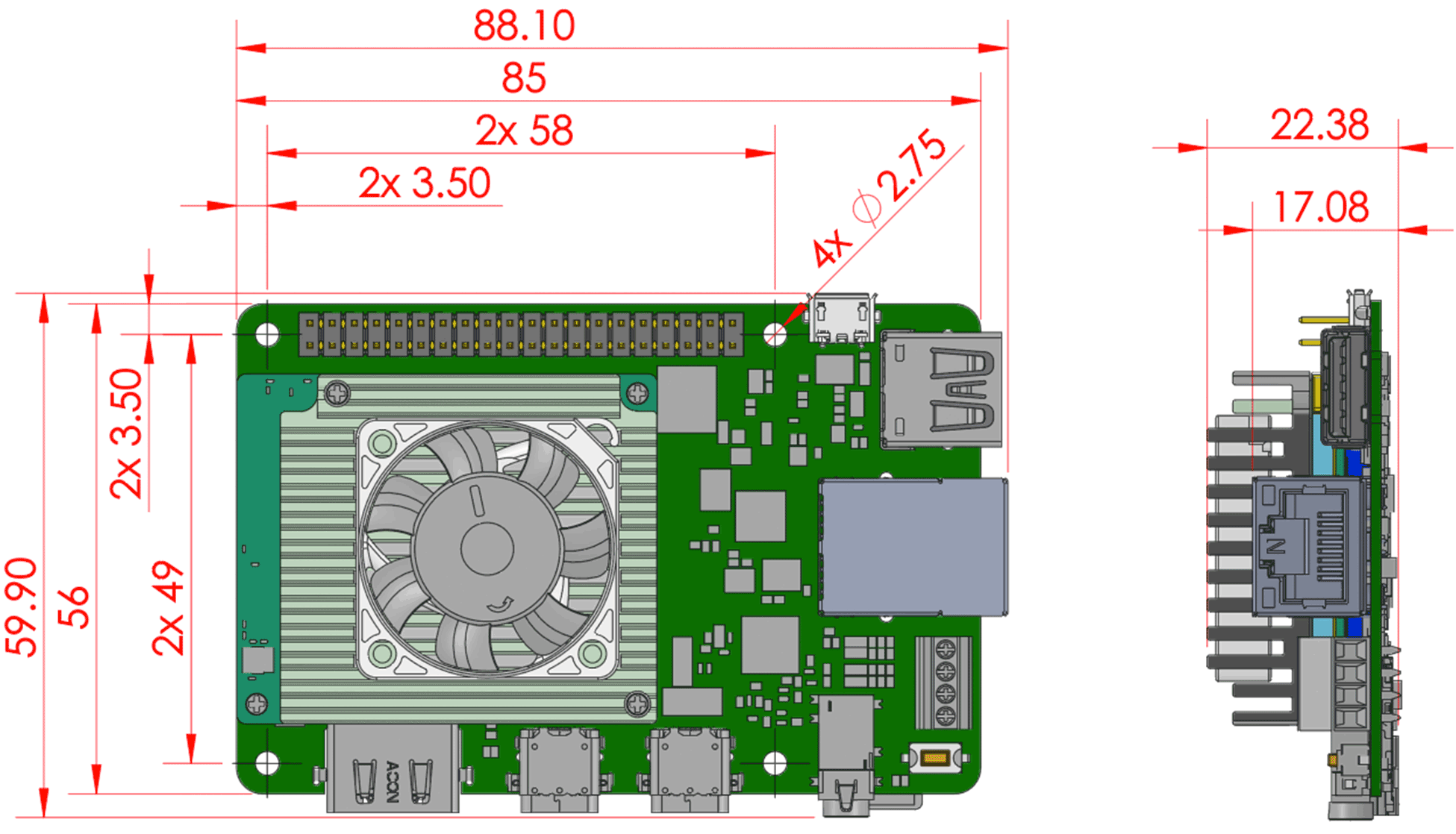
Mechanical dimensions
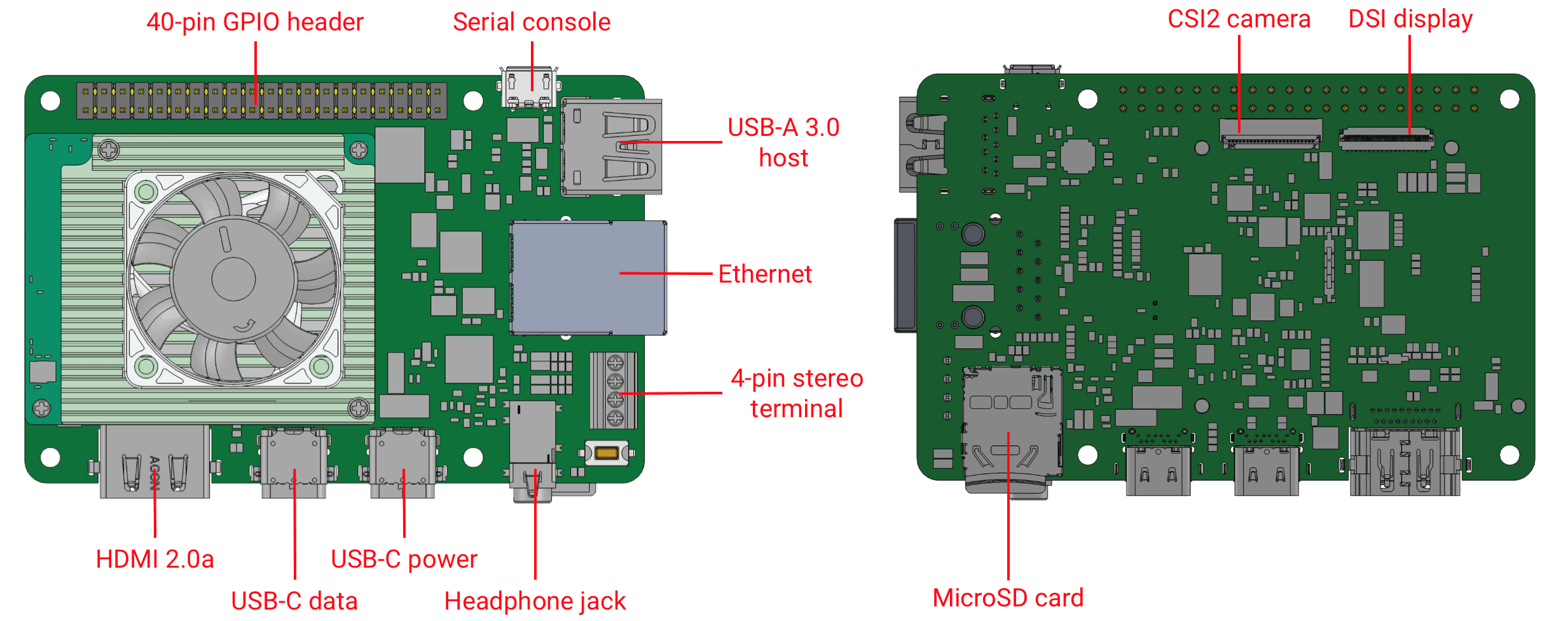
Baseboard connections
The baseboard on the Coral Dev Board provides a variety of connectors as shown in figure 4.
I/O header pinout
All I/O pins on the 40-pin header are powered by the 3.3 V power rail, with a programmable impedance of 40-255 ohms, and a max current of ~82 mA.
All I/O pins have a 90k pull-down resistor inside the iMX 8M SoC that is used by default during bootup, except for the I2C pins, which instead have a pull-up to 3.3 V on the SoM. However, these can all be changed with a device tree overlay that loads after bootup.
You can interact with each pin using standard Linux interfaces such as device files (/dev) and
sysfs files (/sys). For usage information, see Connect to the Dev Board I/O
pins.
| SoC signal name | Baseboard signal | Header pins | Baseboard signal | SoC signal name | |
|---|---|---|---|---|---|
| +3.3 V power | 1 | 2 | +5 V power | ||
| I2C2_SDA | I2C2_SDA | 3 | 4 | +5 V power | |
| I2C2_SCL | I2C2_SCL | 5 | 6 | Ground | |
| UART3_TXD | UART3_TXD | 7 | 8 | UART1_TXD | UART1_TXD |
| Ground | 9 | 10 | UART1_RXD | UART1_RXD | |
| UART3_RXD | UART3_RXD | 11 | 12 | SAI1_TXC | SAI1_TXC |
| GPIO6 | GPIO_P13 | 13 | 14 | Ground | |
| PWM3 | PWM3 | 15 | 16 | GPIO_P16 | NAND_DATA03 |
| +3.3 V power | 17 | 18 | GPIO_P18 | ECSPI2_SCLK | |
| ECSPI1_MOSI | ECSPI1_MOSI | 19 | 20 | Ground | |
| ECSPI1_MISO | ECSPI1_MISO | 21 | 22 | GPIO_P22 | ECSPI2_MISO |
| ECSPI1_SCLK | ECSPI1_SCLK | 23 | 24 | ECSPI1_SS0 | ECSPI1_SS0 |
| Ground | 25 | 26 | ECSPI1_SS1 | ECSPI1_SS1 | |
| I2C3_SDA | I2C3_SDA | 27 | 28 | I2C3_SCL | I2C3_SCL |
| GPIO7 | GPIO_P29 | 29 | 30 | Ground | |
| GPIO8 | GPIO_P31 | 31 | 32 | PWM1 | PWM1 |
| PWM2 | PWM2 | 33 | 34 | Ground | |
| SAI1_TXFS | SAI1_TXFS | 35 | 36 | GPIO_P36 | ECSPI2_SS0 |
| NAND_DATA07 | GPIO_P37 | 37 | 38 | SAI1_RXD0 | SAI1_RXD0 |
| Ground | 39 | 40 | SAI1_TXD0 | SAI1_TXD0 | |
Key:
| Synchronous Audio Interface (SAI) |
Serial Peripheral Interface (SPI) |
General Purpose I/O (GPIO) |
+5 V power |
| Inter-Integrated Circuit (I2C) |
Universal Asynchronous Receiver-Transmitter (UART) |
Ground | +3.3 V power |
Universal Asynchronous Receiver-Transmitter (UART)
Each UARTv2 module supports the following:
- 7- or 8-bit data words, 1 or 2 stop bits, programmable parity (even, odd, or none).
- Programmable baud rates up to 4 Mbps.
- 32-byte FIFO on Tx and 32 half-word FIFO on Rx supporting auto-baud.
Synchronous Audio Interface (SAI)
Each SAI module supports full duplex serial interfaces with frame synchronization, such as I2S, AC97, TDM, and codec/DSP interfaces.
Inter-Integrated Circuit (I2C)
Serial interface for external devices.
Serial Peripheral Interface (SPI)
Full-duplex enhanced Synchronous Serial Interface, with data rate up to 52 Mbit/s. Configurable to support Master/Slave modes, four chip selects to support multiple peripherals.
Pulse Width Modulation (PWM)
Operates on a frequency of 0-66 Mhz. Provides a 16-bit counter and is optimized to generate sound from stored sample audio images. It can drive motors and generate tones. It uses 16-bit resolution and a 4x16 data FIFO to generate sound.
Serial console port
The micro-USB port (see "serial console" in figure 4) provides access to the serial console based on the CP210x USB to UART Bridge Controller. Only Linux and Mac are officially supported for serial console connections, as follows.
Connect with Linux
-
Run the following commands to add the required udev rule:
sudo sh -c "echo 'SUBSYSTEM==\"usb\", ATTR{idVendor}==\"0525\", MODE=\"0664\", \
GROUP=\"plugdev\", TAG+=\"uaccess\"' >> /etc/udev/rules.d/65-edgetpu-board.rules"


sudo udevadm control --reload-rules && udevadm trigger -
Determine the device filename for the serial connection by running this command on your Linux computer:
dmesg | grep ttyUSB
You should see two results such as this:
[ 6437.706335] usb 2-13.1: cp210x converter now attached to ttyUSB0
[ 6437.708049] usb 2-13.1: cp210x converter now attached to ttyUSB1
-
Use the name of the first filename listed as a
cp210x converterto open the serial console connection (this example usesttyUSB0as shown from above):screen /dev/ttyUSB0 115200
Connect with Mac
-
Install the following device driver.
Caution: Before installing the following package, be sure you've applied all available macOS software updates. Otherwise, you might be blocked from installing due to system security that disables the Allow button in System Preferences.Install the CP210x USB to UART Bridge Virtual COM Port (VCP) driver for Mac.
-
Connect with this command:
screen /dev/cu.SLAB_USBtoUART 115200
screen prints Cannot access line '/dev/ttyUSB0', then your Linux user
account is not in the plugdev and/or dialout system group. Ask your
system admin to add your account to both groups, and then restart your computer for it to take
effect.
If you see [screen is terminating], it might also be due to the system groups, or
there's something else wrong with screen—ensure all screen sessions are
closed (type screen -ls to see open sessions), unplug the USB cable from the Dev
Board, and then try again.
HDMI port
This is a full-size HDMI 2.0a port.
By default, the output is locked at a resolution of 1920 x 1080 to avoid GPU pressure and power costs when driving higher resolution displays.
If your display does not support 1920 x 1080, you can change this setting by editing file
at /etc/xdg/weston/weston.ini: In the [output] section, edit the line
mode=1920x1080 to be a resolution of your choice. You may also delete this line completely,
and it will then use the highest resolution supported by the monitor (but doing so can
degrade the overall system performance if it is higher than 1920x1080).
USB 3.0 ports
There are three USB 3.0 ports:
-
USB Type-A host: Operates as a USB 3.0 host that can provide power. Use this port for your peripherals, such as a USB camera.
Caution: Do not connect a device that draws more than 1 A of power or you will brownout the system. -
USB Type-C data: Operates as a USB "on the go" (OTG) device port, so the Dev Board appears as a USB device to a connected host device. Use this port to connect to the shell over USB or to flash the board.
-
USB Type-C power: Use this to power the board with a 2-3 A at 5 V DC connection.
Ethernet port
The Gigabit Ethernet port (RJ45) supports 10/100/1000 Mbps Ethernet/IEEE 802.3 networks.
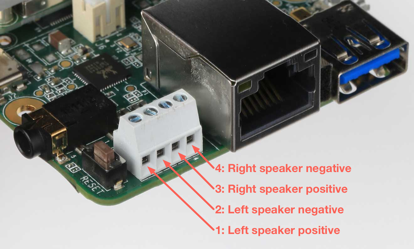
4-pin stereo terminal
We recommend using a 4 ohm, 3 watt speaker. A higher ohmage results in a much quieter output.
The stereo terminal is a 4-pin 2.54 mm-pitch terminal connector for stereo speakers. Wire functions are as follows (from left to right, as shown in figure 5):
- 1: Speaker left positive
- 2: Speaker left negative
- 3: Speaker right positive
- 4: Speaker right negative
MicroSD slot
The MicroSD card meets the SD/SDIO standard, up to version 3.0. It can be used as expanded memory for the system or as the disk for the system image. If the entire system fails, you can use the SD card to reflash U-Boot onto the board (see the flashing instructions).
MIPI DSI display connector
The MIPI DSI display connector is a 39-pin flex cable connector that provides 4 lanes with resolution up to 1920x1080 at 60 Hz. The connector pinout is as follows.
| Pin # | Name | Pin # | Name | |
|---|---|---|---|---|
| 1 | GND | 21 | DSI_TE | |
| 2 | ---TP5 | 22 | --- | |
| 3 | ---TP20 | 23 | V1V8 | |
| 4 | ---TP2 | 24 | --- | |
| 5 | GND | 25 | DISP_LEDA | |
| 6 | MIPI_DSI_D2_P | 26 | DISP_LEDK1 | |
| 7 | MIPI_DSI_D2_N | 27 | DISP_LEDK2 | |
| 8 | GND | 28 | VOP_5p5_CONN | |
| 9 | MIPI_DSI_D1_P | 29 | VON_N5p5_CONN | |
| 10 | MIPI_DSI_D1_N | 30 | LED_PWM | |
| 11 | GND | 31 | GND | |
| 12 | MIPI_DSI_CLK_P | 32 | GND | |
| 13 | MIPI_DSI_CLK_N | 33 | --- TP21 | |
| 14 | GND | 34 | GND | |
| 15 | MIPI_DSI_D0_P | 35 | DISPLAY_I2C_SCL_1V8 | |
| 16 | MIPI_DSI_D0_N | 36 | DISPLAY_I2C_SDA_1V8 | |
| 17 | GND | 37 | DSI_VSP_EN | |
| 18 | MIPI_DSI_D3_P | 38 | DSI_TS_nINT | |
| 19 | MIPI_DSI_D3_N | 39 | DSI_RESETB | |
| 20 | GND |
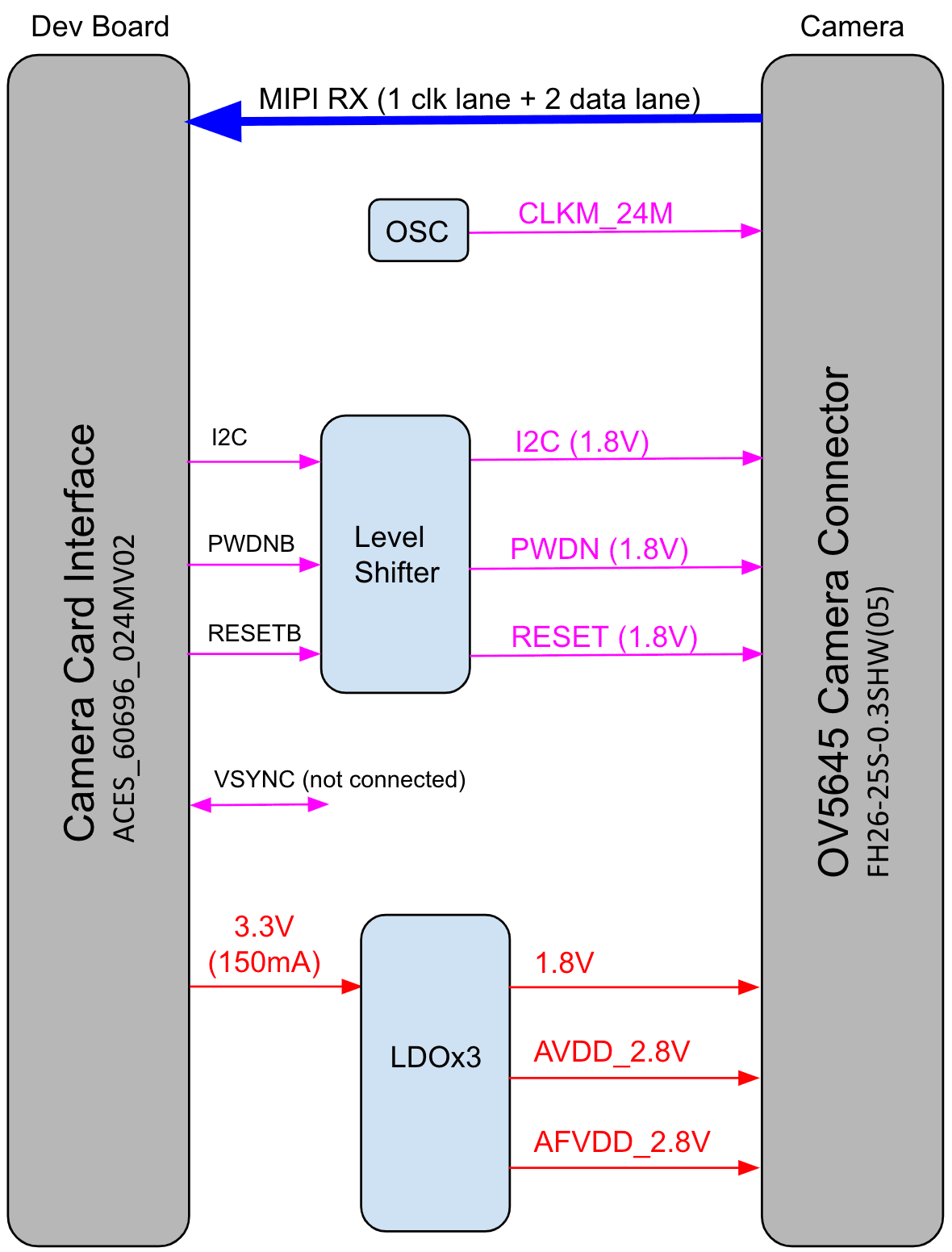
MIPI CSI-2 camera connector pinout
The MIPI CSI-2 camera connector is a 24-pin flex cable connector that's designed for the Coral Camera. The connector pinout is as follows.
| Pin | Name | Pin | Name | |
|---|---|---|---|---|
| 1 | GND | 13 | GND | |
| 2 | MIPI_CSI_D0_N | 14 | MIPI_CSI_D3_N | |
| 3 | MIPI_CSI_D0_P | 15 | MIPI_CSI_D3_P | |
| 4 | GND | 16 | GND | |
| 5 | MIPI_CLK_N | 17 | CAM_PWDNB | |
| 6 | MIPI_CLK_P | 18 | CAM_CLK (NC) | |
| 7 | GND | 19 | GND | |
| 8 | MIPI_CSI_D1_N | 20 | CAM_I2C_SCL | |
| 9 | MIPI_CSI_D1_P | 21 | CAM_I2C_SDA | |
| 10 | GND | 22 | CAM_VSYNC (NC) | |
| 11 | MIPI_CSI_D2_N | 23 | CAM_RESETB | |
| 12 | MIPI_CSI_D2_P | 24 | 3.3V |
System power
The Coral Dev Board must be powered by 2-3 A at 5 V DC using the USB Type-C power port (see figure 4).
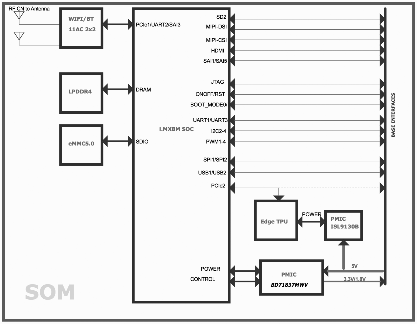
The SoM has one primary PMIC (BD71837MWV) from Rohm for the iMX 8M SoC complex, LPDDR4, eMMC, and Wi-Fi/Bluetooth. It integrates 8 DC-DC buck regulators and 7 LDOs to provide all power rails required by iMX 8M SoC and commonly used peripherals.
Boot mode
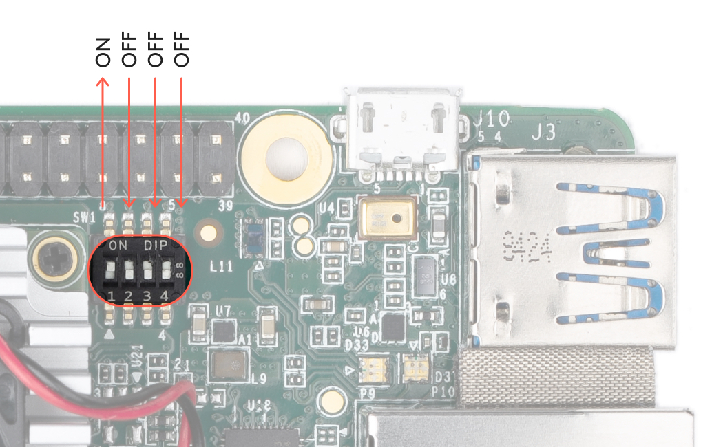
The baseboard includes 4 switches (indicated in figure 7 to control the boot mode. By default, they are set to boot from eMMC. You can change the boot mode as follows.
| Boot mode | Switch 1 | Switch 2 | Switch 3 | Switch 4 |
|---|---|---|---|---|
| Serial download | Off | On | [Don't care] | [Don't care] |
| eMMC | On | Off | Off | Off |
| SD card | On | Off | On | On |
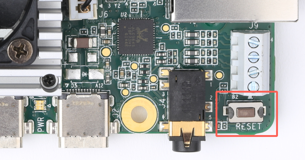
System reset
You can restart the system with the RESET button shown in figure 8.
Software and operation
The Dev Board factory setting includes only the U-Boot bootloader software on the eMMC memory. To use the board, you need to flash the Mendel operating system (a derivative of Debian Linux). For instructions, see the Get started guide.
The Mendel system includes software that's specially-designed for the Dev Board and required to operate the Edge TPU. It also includes Python APIs that make it easy to perform inferences with TensorFlow Lite models.
To learn how to create models and run inferences on the Edge TPU, read TensorFlow models on the Edge TPU.
sudo shutdown now
When the red LED on the Dev Board turns off, you can unplug the power.
LED behavior
The Dev Board has two sets of on-board LED lights: one LED for power status, and a pair of LEDs providing the status of the serial port.
The Ethernet port also has a pair of LED lights.
Power LED
The LED that provides power status is situated between the Power (PWR) and USB On-The-Go (OTG)
ports. It lights up red when the board is powered up and switches off when either power is removed
or the main SoC is shut down (for example, when a sudo shutdown command is issued).
Serial port LEDs
The board has green and yellow LEDs near the serial console connector (USB micro-B), those show TX/RX activity via serial interface. The green LED lights up when there is activity on the RX line (indicating data is being received over the serial interface), while the yellow LED lights up when there is activity on the TX line (indicating that data is being transmitted over the serial interface).
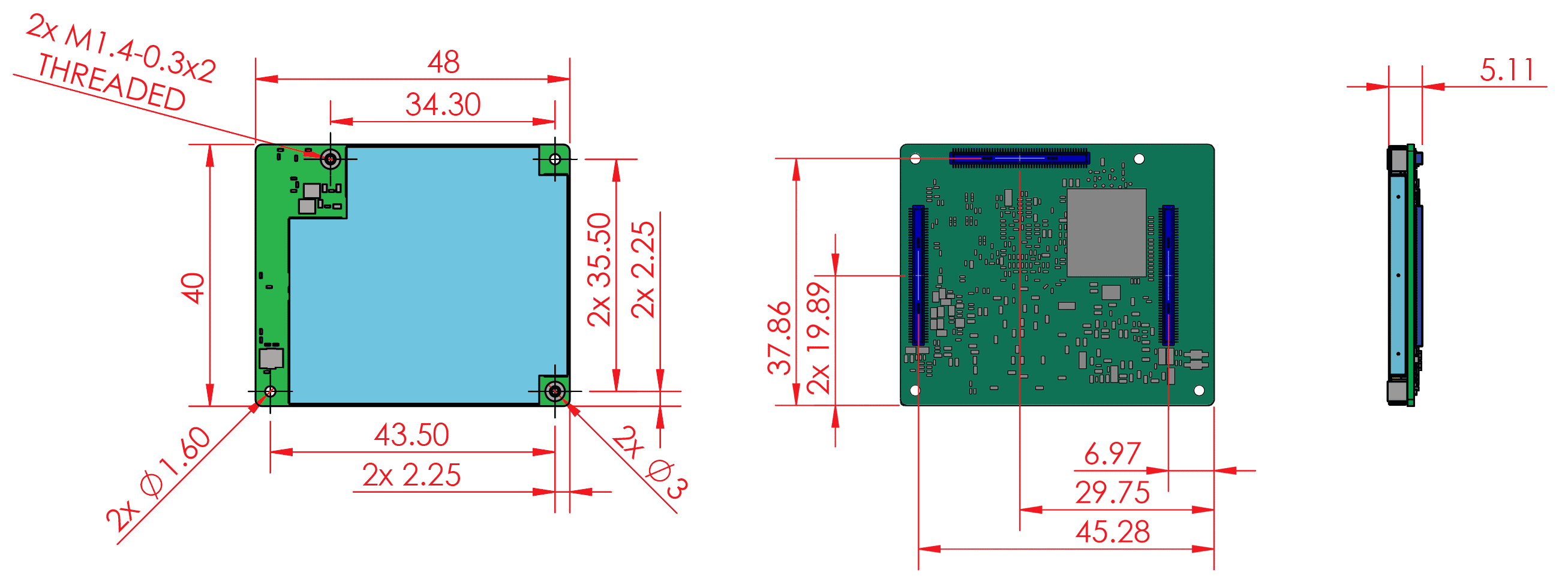
SoM hardware details
The system-on-module (SoM) included with the Dev Board is based on NXP's iMX 8M system-on-chip (SoC) and contains all the essential system hardware, including the Edge TPU and Wi-Fi/Bluetooth radios. It is attached to the Dev Board baseboard with three 100-pin board-to-board connectors.
Figure 9 shows the dimensions of the SoM.
Recommended operating conditions
To ensure reliable operation and performance, the board should operate in the following environment:
- Temperature: 0-50° C
Thermal solution
To maintain functional heat levels the Dev Board includes a heat sink and a fan with the following specifications:
- Speed: 9k RPM
- Airflow: 138 LPM (4.9 CFM)
- Voltage: 5 V DC
- Power (peak): 0.65 W
- Static pressure: 42 Pa (0.17 in-H2O)
Environmental and mechanical reliability tests
| Test | Conditions | Verified |
|---|---|---|
| Temp cycling | Non-op, -40° C (LT) to 85° C (HT), 7 minute ramp, 23 minutes dwell, 60 minutes/cycle | 200 cycles |
| Heat soak | Non-op, 85° C @ 85% RH | 200 cycles |
| Audio jack cycling | 50% manual plug/unplug, 50% uniaxial machine plug/ unplug | 1000 cycles |
| HDMI cycling | Manual plug/unplug | 100 cycles |
| MicroSD cycling | Manual plug/unplug | 100 cycles |
| Vibration | 3 axes (X, Y and Z), 15 minutes per axis, 10-500 Hz. Amplitude: 2.16 Grms | 45 minutes |
| USB-C connector cycling | Manual plug/unplug | 1000 cycles |
| USB-A connector cycling | Manual plug/unplug | 1000 cycles |
| Micro USB connector cycling | Manual plug/unplug | 1000 cycles |
| Fan run life | 40°C, 65% RH | 70k hours |
Certifications
| Country | Agency |
|---|---|
| USA | FCC |
| European Union | CE |
| Hong Kong | CE |
| Japan | VCCI |
| Korea | KC |
| Ghana | NCA |
| Taiwan | BSMI/NCC |
| Australia | RCM |
| New Zealand | RCM |
| India | WPC |
| Thailand | NBTC |
| Singapore | IMDA |
| Oman | TRA |
| Philippines | NTC |
Schematic and layout files
| File | Description |
|---|---|
| Coral-Dev-Board-baseboard-schematic.pdf | Baseboard schematic in PDF |
| Coral-Dev-Board-baseboard-schematic-Altium.zip | Baseboard schematic files in Altium format |
| Coral-Dev-Board-baseboard-layout-Allegro.brd | Baseboard CAD layout in BRD format |
| Dev Board.STEP | Dev Board (baseboard and SoM) 3D CAD file in STEP format |
Document revisions
| Version | Changes |
|---|---|
| 1.7 (December 2022) |
|
| 1.6 (July 2020) |
|
| 1.5 (June 2020) |
|
| 1.4 (April 2020) |
|
| 1.3 (January 2020) |
|
| 1.2 (August 2019) |
|
| 1.1 (August 2019) |
|
| 1.0 (June 2019) |
|
| Beta (March 2019) | Initial release |
Is this content helpful?